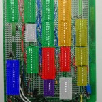
The Design – principles

As I posted before, I was thinking of using VGA for a while, but my first real breakthrough in the design was the thought that rather than just reading directly off of the chip I could read one byte off, store that in a latch, then with a 8-to-1 chip, I could read one bit at a time off of that and display it.  It meant, more importantly to me, that only three 74 series chips would be run at 25mhz, and all the others would be run at 3.125 Mhz, which meant no high-speed problems (which I read I should avoid). It also meant that my need for fast ram would be cut, and I’d have a tonne of time to do things, but I had already found and bought a fast ram chip. So with that, I devised three other principles, which I’d use in the design.

My Basic Principles;

  • TTL  and fast TTL at that, S, ACT, or F
  • Give the ram as much room as possible, but get fast SRAM
  • Simple bus management

Fast TTL

One of my biggest fears was that when it was finished, the various latencies due to propagation etc would cause some bug (Turns out this was true, but different then I expected). I didn’t have a great logic analyzer or scope, so I wanted to keep these as small as possible. Also, power and cost wasn’t going to be an issue, I wanted to not have to dance too much around delays. So I chose chips who’s delays were in the range of 1-10ns. In hind-site it seems as if didn’t really matter that much, if you have bus contention, 2-4ns is enough time to mess everything up and the design was simple enough that delays could really stack up.

Why TTL? Well, as I found, and is probably best suited for a post of its own, when looking for chips I found the most availability and speed in the TTL line. CMOS was often unavailable, it sucked reading about a great chip, then not being able to find it, or if it was available, it was surface mount and expensive.

Ram Speed

In looking at Rams, I found a really fast 12ns 256kb SRAM. VGA has a clock speed of 25.125 Mhz, which corresponds to roughly 40ns between clock cycles. I wanted RAM that was faster than one refresh, in case as I ironed out the design I needed to fall back to that. Even though my design could handle ram 10x slower, I didn’t want to be boxed into that.

Simple Bus Management

This was one of the biggest issues I had, how to communicate between the Arduino and the Card. This was my biggest shortfall as well. I thought the simplest approach was a ‘ram ready’ signal. I would send this from the card when I had enough time to expose the internal bus to the arduino. I realize now this was a big mistake, but at the time, it meant just some transceivers. The thought came to me that the SX-28 that was handling the bus availability would know when the bus would be ready, so it could signal to arduino that it was ok to send, and the arduino could just loop waiting for the signal to know it could progress to the next byte to be stored. At first I thought this could happen at the end of every scan line. But that was silly on my part, it turns out it was only really available a couple of times during the vertical refresh areas.

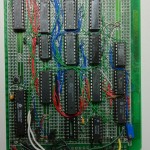
 

Arduino VGA Frame interface project.

Here is my VGA card in its completed Glory. Over the next few posts I’ll explain some of the theory behind it, and more importantly, I’m going to try to describe some newbie electronics issues I met and how I overcame them. When I was building this I found myself constantly researching in many books to figure things out. My mind sometimes is too rebellious, and when told, do it this way, it asks, ‘Why?’. It turns out it’s really difficult to find the answers in many cases, so I’ll try to dump as much as I can on this blog.


Electronics, A personal history.


I have always been interested in electronics,but I always found myself blocking on really sitting down and learning electronics, rather than just building kits.  I remember spending hours and hours building circuit after circuit with a Radio Shack 75-in-1 kit when I was 10-14 years old. I hoped to eventually learn why this resistor needed to be there or this capacitor. Reading through the booklet included I kind of understood, but I never really found a project that captivated my interest. During highschool, my electronics class consisted of figuring out the correct voltages and thickness of pencil lead that would melt staples or anything else we could find around. Well, either that or arguing Ford vs Chevy vs Mopar. I tried to build a ‘de-scrambler’ for TV, but lets say my teacher while ‘energetic’ either had his hands full with tool thieves or just wanted to appease them so he never really got around to teaching any serious theory or any help with my project. It was there I found out that car speaker box construction was ‘electronics’.

At my first job outside of college I got a look at a different view of electronics. There at Cymbolic Sciences, I was surrounded by electrical engineers and since we designed all our own processor boards, I just started hearing about Microcontrollers and FPGAs. I never got my hands on one, but my job brought me into contact with Matlab and more importantly, Simulink. Simulink can be used for many things, process simulation being one of the main things, but I found some elemental logic building blocks within it that piqued my interests. Using it this way it reminds me now of programs like Logisim. I remember spending one night (I worked the 4pm to 1am shift), playing around figuring out how to get the NAND gates to act as a simple flip/flop. Then I built a multiplexor and de-multiplexor out of logic and glued these with the flip/flops into a 64bit RAM block. Then I used that block in a different simulation… and well, I ran out of the 64 MBs of RAM my laptop had.

I would over the course of a the years experiment with different logic simulation programs; I got my wife to buy a copy of NI’s Circuit design suite using her student discount for example, but I was always stuck on ‘what to make’.

Then, a few years ago, my friend Delaney introduced me to a book, “The Black Art of Video Game Console Design”. I immediately was inspired, in a few days, my Xgamestation Pico was delivered and me and Delaney were planning many projects. I was most interested in writing to video. The Pico is around the idea of using a microcontroller (the SX-28)to handle all the video timing signals itself. This meant that in your program (written in either sx-28 assembly or a primitive ‘basic’) you had to deal with 80% of your program working around video timing and display. I got the idea of building a logic based video driver that the pico could write to and it would do all the video display. The first design used NTSC, but I found the color handling of NTSC to be really discouraging. That’s when Delaney told me what he learned about VGA. If you could handle the speed, with VGA you just had to control three voltages for the three colors, and you just need to bound two control lines to handle the vertical and horizontal syncs. Aha, I thought, here is the answer.

Around that time, I went to a Maker’s faire, I think it was the 2nd one, and saw the Arduino projects. I was trying to work around  the lack of control lines of the sx-28, and the pain of programming in assembly. I was considering the sx-48, but it was surface mount only, and I didn’t want to work with that… yet. But here, I could just buy an Arduino Mega, which was literally right in front of me, and I’d have as many control lines as I’d want, all with a nice little header to plug into. Plus, a really nice programming interface that was C based, instead of assembly. That’s when my VGA based video circuit solidified.